Task 08 - Templates type file (Optional)
Estimated Time to Complete: ~15 minutes
In this task you'll use templates of type file to reference external template files that use Terraform templating syntax (.tftpl). File templates are the right tool when you need loops, conditionals, or complex structures that plain YAML can't express cleanly.
For detailed documentation, see: IOS XE as Code Template Documentation
What you'll learn
By the end of this task you will have:
- Authored a
.tftpltemplate file using Terraform templating syntax - loops (%{ for }), variable interpolation (${ }), whitespace stripping - Referenced the file template from a device-level configuration on
border - Deployed an eBGP session to the pre-configured
isppeer (AS 65001) and seen the route to8.8.8.0/24appear
File templates
File templates reference external .tftpl files that use Terraform templating syntax. This is ideal for:
- Dynamic configurations: Configurations with loops and conditionals
- Complex structures: Multi-line configurations that need programmatic generation
Terraform Templating Syntax:
| Syntax | Purpose | Examples |
|---|---|---|
${ } |
Variable interpolation | ${BGP_AS_NUMBER} |
%{ } |
Control structures | |
%{ for } |
For loop | %{ for NEIGHBOR in BGP_NEIGHBORS }, %{ endfor } |
%{ if } |
Conditional | %{ if OPTION == "A" }, %{ else }, %{ endif } |
~ |
Whitespace stripping | %{~ endfor ~} |
Template Types (reminder):
| Type | Description | Use Case |
|---|---|---|
| model | YAML-based configuration template | Standard configurations (VLANs, ACLs, etc.) ← Task07 |
| file | External .tftpl template files |
Dynamic configs with variables ← This task |
| cli | Raw CLI commands | IOS XE features not in the IOS XE as Code data model ← Task09 |
Three patterns side-by-side: device groups, model templates, file (.tftpl) templates
By Task 08 you've now seen three distinct mechanisms for reusing
configuration across devices: the device groups from
Task 04, the model templates
from Task 07, and the file
(.tftpl) templates introduced in this task. They look superficially
similar - all three reduce duplication - but they answer different
questions and compose differently. The diagram below summarizes the
distinction; the prose underneath walks through each one.
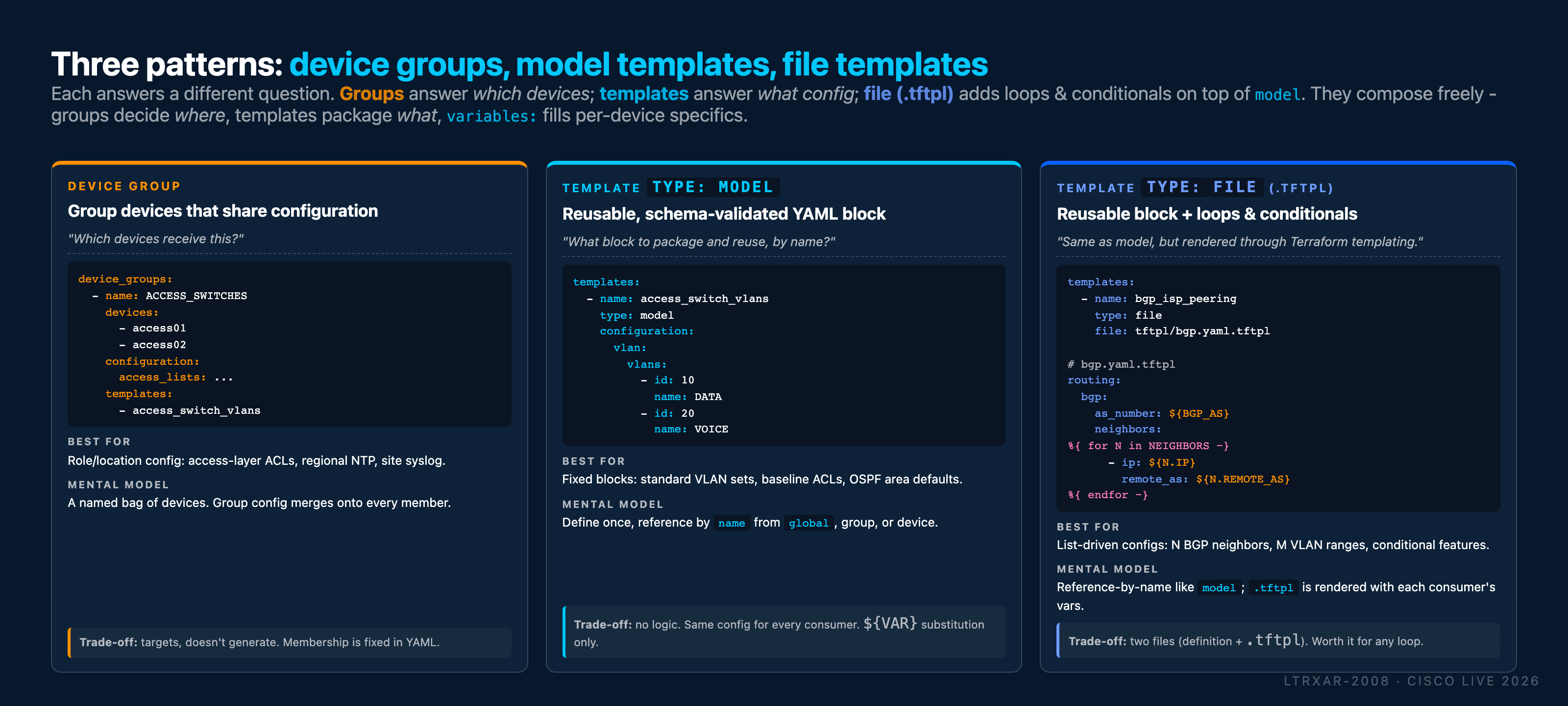
Each pattern answers a different question.
- Device group - answers "Which devices receive this configuration?"
A device group is a named bag of devices (in this lab,
ACCESS_SWITCHES = [access01, access02]). Configuration written directly under the group'sconfiguration:key merges onto every member at apply time. A group can also reference templates, which are then expanded for each member. Best for: role-based or location-based config - access-layer ACLs, regional NTP/timezone, site-wide syslog targets. Trade-off: membership is fixed in YAML; the group definition itself doesn't generate any configuration, it just targets it. - Template
type: model- answers "What block of config do I want to package and reuse, by name?" A model template is a chunk of standard NaC YAML wrapped in a name. You define it once (e.g.access_switch_vlansfrom Task 07), then reference it by name from any combination ofglobal, a device group, or individual devices. Because it's plain YAML against the data model, the schema validates it (Task 10) just like inline configuration. Best for: fixed, repeatable blocks - standard VLAN sets, baseline ACLs, common interface profiles, OSPF area defaults. Trade-off: no logic. Every consumer of the template gets the same config (variables can substitute simple values like${HOSTNAME}, but there are no loops or conditionals). - Template
type: file(.tftpl) - answers the same "what block?" question asmodel, but renders the block through Terraform's templating engine first. The template definition lives in YAML (templates: - name: ...; type: file; file: tftpl/bgp.yaml.tftpl), and the actual configuration body lives in a separate.tftplfile that supports variable interpolation (${VAR}), loops (%{ for x in LIST }), and conditionals (%{ if ... }). At apply time, NaC reads each consumer'svariables:block and renders the.tftplagainst those values, then merges the rendered YAML into the data model. Best for: list-driven configs - N BGP neighbors per device, M VLAN ranges, conditional features keyed off device variables. Trade-off: two files instead of one (the YAML template definition plus the.tftplbody). The moment you need a loop or conditional, the extra file is worth it.
They compose, they don't compete. A device group can apply
both a model and a file template to its members at the same
time, and a single device can override what the group applies. The
canonical pattern in production is: groups decide where,
templates decide what, and variables fill in the per-device
specifics (IP, AS number, neighbor list).
Quick mental rule
- Need to point a chunk of configuration at a set of devices? Reach for a device group.
- Need to package and name a chunk of configuration so multiple
places can reference it? Reach for a
modeltemplate. - Need that same packaged chunk to expand into a list or react
to per-device variables with loops/conditionals? Promote the
modeltemplate to afiletemplate.
Use case: BGP configuration on border switch
In this example, you'll configure BGP on the border switch for peering with ISP providers. The template will use variables to define BGP neighbors dynamically.
Lab Scenario
The border switch connects to two ISP providers:
- isp (
198.18.100.1) - Currently active and pre-configured in the lab - isp-x (
198.18.100.5) - Placeholder for a future connection
When you verify the BGP configuration, the isp neighbor will show as Established, while isp-x will show as Idle (since the remote end is not yet configured).
Step 1: Create the template file
First, create the tftpl directory and the template file using your WSL Ubuntu terminal:
Then open tftpl/bgp.yaml.tftpl in VS Code and add the following content:
routing:
  bgp:
    as_number: ${BGP_AS_NUMBER}
    log_neighbor_changes: true
    neighbors:
%{ for NEIGHBOR in BGP_NEIGHBORS ~}
      - ip: ${NEIGHBOR.IP}
        remote_as: ${NEIGHBOR.REMOTE_AS}
        description: "${NEIGHBOR.DESCRIPTION}"
        timers_keepalive: 60
        timers_holdtime: 180
        timers_minimum_neighbor_holdtime: 30
%{ endfor ~}
    address_family:
      ipv4_unicast:
        neighbors:
%{ for NEIGHBOR in BGP_NEIGHBORS ~}
          - ip: ${NEIGHBOR.IP}
            activate: true
%{ endfor ~}
This template uses:
routing: bgp:- BGP configuration must be nested underroutingper the IOS XE as Code data model${BGP_AS_NUMBER}- Variable for the local AS number%{ for NEIGHBOR in BGP_NEIGHBORS }- Loop through list of neighbors (twice, in two sections)%{ endfor }- End of the loops~- Whitespace stripping, cleans up extra spaces/newlines in the rendered output${NEIGHBOR.IP},${NEIGHBOR.REMOTE_AS},${NEIGHBOR.DESCRIPTION}- Access neighbor variables for attributes
Template Location
The file bgp.yaml.tftpl is located in the tftpl/ folder, outside of the main data/ folder. Even though the tftpl/ folder is not included in the module configuration in main.tf, the template's content is still accessible because it is referenced in the template definition file that you'll create next.
Step 2: Create the template definition file
Create a new file data/templates/bgp.nac.yaml that defines the template:
Then open data/templates/bgp.nac.yaml in VS Code and add the following content:
---
iosxe:
  templates:
    - name: bgp_isp_peering
      type: file
      file: tftpl/bgp.yaml.tftpl
This separates the template definition from the device configuration, making it easier to manage and reuse.
Step 3: Apply the template to border device
Now open the existing data/devices/border.nac.yaml file in VS Code (this was created as a placeholder in Task05) and add the template reference with variables:
---
iosxe:
  devices:
    - name: border
      host: 198.18.130.20
      variables:
        HOSTNAME: border
        BGP_AS_NUMBER: 65000
        BGP_NEIGHBORS:
          - IP: 198.18.100.1
            REMOTE_AS: 65001
            DESCRIPTION: eBGP to isp - Production
          - IP: 198.18.100.5
            REMOTE_AS: 65002
            DESCRIPTION: eBGP to isp-x - Future Migration
      templates:
        - bgp_isp_peering
      configuration:
        interfaces:
          ethernets:
            - type: GigabitEthernet
              id: "1"
              description: "isp G0/1"
              shutdown: false
              ipv4:
                address: 198.18.100.2
                address_mask: 255.255.255.252
What's in this configuration:
devices:- Device-specific configurationname: border- The border switch where BGP will be configuredvariables:- Variables that will be substituted into the templatetemplates:- References thebgp_isp_peeringtemplate defined intemplates/bgp.nac.yamlconfiguration: interfaces- Interface configuration for the ISP connection. Refer to the IOS XE as Code data model
Variable Breakdown:
BGP_AS_NUMBER: 65000: border switch AS numberBGP_NEIGHBORS: List of ISP neighbors:- isp (65001): Active production peer
- isp-x (65002): Placeholder for future network migration
IP,REMOTE_AS,DESCRIPTION: Attributes used in the template for each neighbor
Device-Level Templates
Templates can be applied directly to individual devices, as shown here. This is ideal when a template is specific to a single device. For templates shared across multiple devices, you can use device groups (as shown with VLANs in Task07).
Step 4: Deploy the configuration
Open your WSL Ubuntu terminal and run the following steps:
Step 1: Navigate to your project directory:
Step 2: Optionally, preview the changes Terraform will make:
Step 3: Apply the configuration:
When prompted, type yes to confirm the deployment.
View the Merged Model
After running terraform apply, open the model.yaml file in VS Code to see how the BGP template file is rendered with your variables and merged into the complete data model. This shows exactly what configuration will be applied to the device.
Step 5: Verify BGP configuration
Expected: Idle for 30-60 seconds, then Established
BGP sessions do not come up instantly. After terraform apply finishes,
expect a 30-60 second window before the neighbor state transitions
through Idle -> Active -> OpenSent -> Established. If your
first show ip bgp summary looks idle, wait a minute and run it
again - this is normal protocol behavior, not a failure.
Use Solar-PuTTY to connect to the border switch and verify the BGP configuration:
border#show ip bgp summary
BGP router identifier 198.18.130.20, local AS number 65000
...

Neighbor        V           AS MsgRcvd MsgSent   TblVer  InQ OutQ Up/Down  State/PfxRcd
198.18.100.1    4        65001      23      23        2    0    0 00:16:54        1
198.18.100.5    4        65002       0       0        1    0    0 never    Idle
border#
Understanding the output
| Neighbor | Status | Explanation |
|---|---|---|
| 198.18.100.1 (isp) | Established (shows prefix count) | Active peer - isp is pre-configured in the lab |
| 198.18.100.5 (isp-x) | Idle | Expected - isp-x is a placeholder for future migration |
The isp neighbor shows as Established with 1 prefix received, while isp-x shows as Idle since the remote end is not configured. This is expected behavior in this lab. In real-world scenarios, you often pre-configure BGP neighbors before the remote end is ready. This allows for seamless cutover during network migrations.
Lab BGP configuration
You can find the pre-configured BGP settings on the isp device in Appendix IV of this lab guide.
Advertised network
The isp neighbor is pre-configured in the lab to advertise the network 8.8.8.0/24 to the border switch, to simulate internet connectivity. 8.8.8.8 is a loopback address configured on the isp device.
You can verify the received route with (same 30-60 second convergence window applies):
border#show ip route
Codes: L - local, C - connected, S - static, R - RIP, M - mobile, B - BGP
...

Gateway of last resort is 198.18.128.1 to network 0.0.0.0

S*    0.0.0.0/0 [1/0] via 198.18.128.1
      8.0.0.0/24 is subnetted, 1 subnets
B        8.8.8.0 [20/0] via 198.18.100.1, 00:20:04
      198.18.100.0/24 is variably subnetted, 2 subnets, 2 masks
C        198.18.100.0/30 is directly connected, GigabitEthernet1
L        198.18.100.2/32 is directly connected, GigabitEthernet1
C     198.18.128.0/20 is directly connected, GigabitEthernet2
      198.18.130.0/32 is subnetted, 1 subnets
L        198.18.130.20 is directly connected, GigabitEthernet2
border#
Advanced challenge - for learners who finish early
Skip this if you're running short on time
This is an optional extension inside an already-optional task. Come back to it if you've completed the recommended path and still have time left. If not, the same challenge is repeated in the Conclusion as something to try at home.
The goal: extend border so that traffic from host01 / host02 can actually reach the "internet" via the ISP BGP peering you just configured. Right now the BGP session is up and advertising 8.8.8.0/24, but border has no interface facing the host subnet, so nothing from the hosts can get there.
| Host | IP address | Default gateway |
|---|---|---|
host01 |
192.168.100.100/24 | 192.168.100.1 |
host02 |
192.168.100.200/24 | 192.168.100.1 |
Your job: add an interface configuration on border so that GigabitEthernet3 (facing the host network) has IP 192.168.100.1/24. The hosts are already configured with that IP as their default gateway.

Primary verification (easy path - just SSH into border):
You should see GigabitEthernet3 up with 192.168.100.1/24, and 8.8.8.0/24 as a BGP-learned route via the ISP neighbor.
End-to-end verification via CML console (more work, more satisfying)
To prove actual end-to-end reachability, ping 8.8.8.8 from inside one of the hosts:
- Open the CML web interface: https://198.18.130.34/login.
- Log in with
guest/CiscoLive. - Click on NAC IOSXE-AS-CODE Topology.
- Right-click host01 → Console → Open Console.
- Log in with
cisco/cisco. - Run:
ping 8.8.8.8. - Repeat for
host02.
This takes a minute to set up but is the only way to confirm the full end-to-end path from host → gateway → BGP → ISP loopback.
Try it yourself first. You've seen every Network as Code concept you need to solve this - per-device config, interface definitions, and the same ethernets list you just used for GigabitEthernet1. Browse the Ethernet data model docs if you get stuck.
Solution
Open data/devices/border.nac.yaml in VS Code and extend the interfaces.ethernets list with a second entry for GigabitEthernet3:
---
iosxe:
  devices:
    - name: border
      host: 198.18.130.20
      variables:
        HOSTNAME: border
        BGP_AS_NUMBER: 65000
        BGP_NEIGHBORS:
          - IP: 198.18.100.1
            REMOTE_AS: 65001
            DESCRIPTION: eBGP to isp - Production
          - IP: 198.18.100.5
            REMOTE_AS: 65002
            DESCRIPTION: eBGP to isp-x - Future Migration
      templates:
        - bgp_isp_peering
      configuration:
        interfaces:
          ethernets:
            - type: GigabitEthernet
              id: "1"
              description: "isp G0/1"
              shutdown: false
              ipv4:
                address: 198.18.100.2
                address_mask: 255.255.255.252
            - type: GigabitEthernet
              id: "3"
              description: "host network G1/0/3"
              shutdown: false
              ipv4:
                address: 192.168.100.1
                address_mask: 255.255.255.0
Run terraform apply, then verify with the show commands above. For bonus points, ping 8.8.8.8 from host01 via CML console.
What you've accomplished
- ✅ Created a
.tftpltemplate file with Terraform templating syntax intftpl/folder - ✅ Created a separate template definition file (
templates/bgp.nac.yaml) - ✅ Used variable interpolation (
${ }) for dynamic values - ✅ Used loops (
%{ for }) for multiple BGP neighbors - ✅ Applied templates at device level to the border switch
- ✅ Configured BGP peering on border switch for ISP connectivity
What's next
Task 09 covers the cli template type (raw CLI lines, last-resort for
features not yet in the data model). If you've seen enough of the
template story, skip ahead to
Task 10 - Schema validation.
← Previous: Task 07 - Templates 'model' · Next: Task 09 - Templates 'cli'